Amplifier linearity pertains to the amplifier’s linear correlation between input signal power and output signal power. This correlation would directly correspond to the amplifier’s gain which is measured in dB (decibels).
Gain (or Power Gain) is defined as 10 X log (RF output power / RF input power). Higher the gain on an input signal means higher power output power.
All RF amplifiers operates within a frequency range and amplifies input RF signals across the defined spectrum, but this increase or gain is not consistent across the band. Nevertheless, most amplifiers experience a reduction in gain as frequency increases, ultimately leading to a decline in gain at higher frequencies. Designing a RF amplifier to work efficiently at higher frequencies more than 6GHz gets difficult due to power losses at higher frequencies. Chicago based RF amplifier manufacturer Elite RF has years of experience in designing high frequency amplifiers as well as high power amplifiers.
Two crucial measurements come into play when assessing the linearity of an RF power amplifier: the third-order intercept IP3 point and the 1-dB compression (P1dB) point. These parameters enable the assessment and comparison of power amplifier specifications and performance. Every engineer must match the amplifier specifications with their own project requirements before buying a RF amplifier. Some additional parameters to consider are efficiency, noise, and input/output impedances.
Linear amplifiers are categorized into class A or class AB. Class A operation is favoured when maximum linearity is the objective, but it comes with the drawback of poor efficiency, often falling below 20% in practice. To enhance efficiency, class AB amplification is employed. However, class AB biassing introduces signal distortion and generates harmonics and intermodulation products.
Lets’ talk about P1dB that is one of the many crucial factors for Class AB amplifiers.
P1DB COMPRESSION
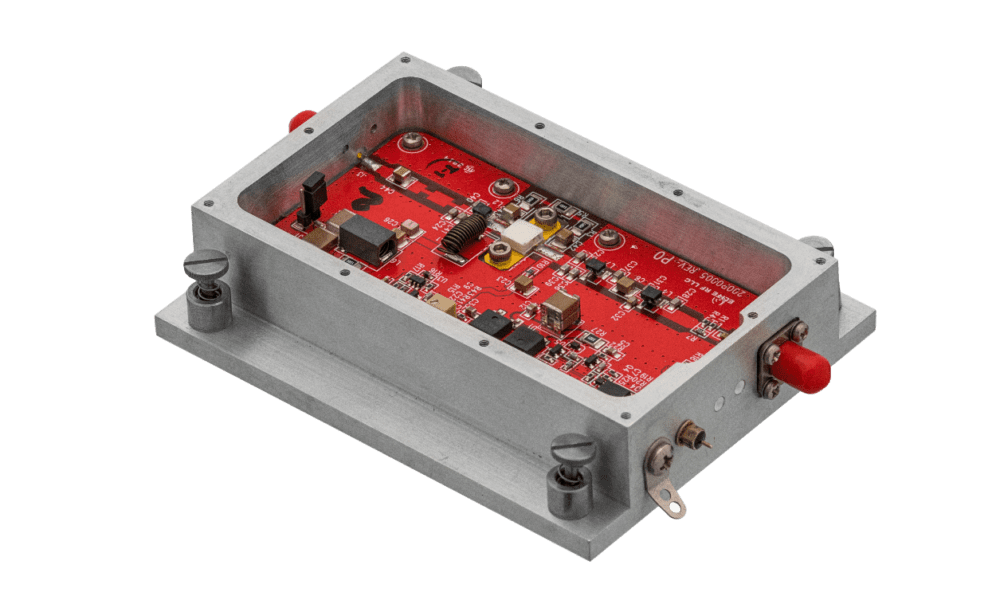
The majority of the Class AB RF amplifiers exhibit a fixed gain within a specific frequency band, as exemplified by the RF amplifier presented below. When plotting output power versus input power, a linear relationship becomes evident (Fig. 1). The slope of the line signifies the gain. As input power escalates, there comes a point at which the gain initiates a decline. This marks the onset of compression, where further increases in output cease with increasing input. The gain flattens, indicating that the amplifier has reached saturation. Its response becomes non-linear, leading to signal distortion, generation of harmonics, and intermodulation products.

It is crucial to pinpoint the juncture at which compression begins to prevent distortion. This is the input power level that triggers a 1-dB decrease from the typical linear gain specification. The 1-dB decrease can be specified either as the input level causing it or as the output power where the 1-dB drop is observed.
The determination of the 1-dB point involves driving the amplifier with a continuous wave (CW) signal at the desired frequency. The input level is progressively increased while plotting the output power.
About Elite RF
Elite RF understands that one size does not fit all. That’s why we work closely with each client to design and deliver RF power amplifiers tailored to our customer’s specific needs. For us,
collaboration at every step of our customer journey is the key to our success. Our core
executive team has more than a century of combined experience with power amplifier design.
Now, you can put our experience to work for you. For more details, visit www.eliterfllc.com